GTA Le Mans Number 03 has a new owner!!

A place to showcase your pride and joy

Moderators: eastlmark, BIG_MVS, Test Moderator

User avatar
User

coopercobra

Rank

Non Member

Posts

88

Joined

Sat Jun 04, 2011 9:50 pm

Location

Llandegla


Has thanked: 1 time
Been thanked: 1 time

Postby coopercobra » Mon Mar 19, 2012 6:50 pm

Had to tackle this myself recently and took a pic of the component parts -

Image

As Andy says, go gently and all should be ok. The triangular (red on mine) casting is what the two screws go into, and off this mounts the motor 'bucket' and then the glass clips over.
User avatar
User

PaulC1959

Rank

Non Member

Posts

1147

Joined

Sun Oct 15, 2006 8:56 pm

Location

Bedfordshire


Has thanked: 10 times
Been thanked: 6 times

Postby PaulC1959 » Mon Mar 19, 2012 10:48 pm

darrenbiggs wrote:Paul,

I think I've got a spare mirror switch in the garage if you need to test it. I'd need to see if I can dig it out though.

Cheers

Darren


Thanks Darren

I will give you a shout if I need it. :wink:

Paul.
Venturi 260 - Saphir (Bleu)
Renault Sport Megane 230 F1 Team R26 - Liquid Yellow
Renault Sport Clio 197 - Ultra Red
Renault Megane Maxim 1.5 DCi - Extreme Blue (Daily Runner)
Minari RS - Coral Red
Smart Roadster Coupe 80 - Spice Red
User avatar
User

PaulC1959

Rank

Non Member

Posts

1147

Joined

Sun Oct 15, 2006 8:56 pm

Location

Bedfordshire


Has thanked: 10 times
Been thanked: 6 times

Postby PaulC1959 » Mon Mar 19, 2012 10:51 pm

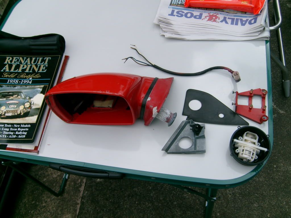
coopercobra wrote:Had to tackle this myself recently and took a pic of the component parts -

Image

As Andy says, go gently and all should be ok. The triangular (red on mine) casting is what the two screws go into, and off this mounts the motor 'bucket' and then the glass clips over.


Thanks for that. :D

I will have a look at the weekend.

Paul. :wink:
Venturi 260 - Saphir (Bleu)
Renault Sport Megane 230 F1 Team R26 - Liquid Yellow
Renault Sport Clio 197 - Ultra Red
Renault Megane Maxim 1.5 DCi - Extreme Blue (Daily Runner)
Minari RS - Coral Red
Smart Roadster Coupe 80 - Spice Red
User avatar
User

andyh877

Rank

Non Member

Posts

3709

Joined

Mon Apr 18, 2005 7:11 am

Location

Alpine France


Has thanked: 1 time
Been thanked: 5 times

Postby andyh877 » Tue Mar 20, 2012 6:44 am

that motor unit looks very similar to the one in my VW Van Mirrors... wil check later..
User avatar
User

PaulC1959

Rank

Non Member

Posts

1147

Joined

Sun Oct 15, 2006 8:56 pm

Location

Bedfordshire


Has thanked: 10 times
Been thanked: 6 times

Postby PaulC1959 » Tue Mar 20, 2012 6:05 pm

andyh877 wrote:that motor unit looks very similar to the one in my VW Van Mirrors... wil check later..


Thanks Andy.

I wouldn't be surprised as small manufacturers would surely look for who is making what and make it fit, in the same way as Venturi used the Porsche 964 Catalytic convertor for their 260 APC. Saves re-inventing the wheel?

Paul. :wink:
Venturi 260 - Saphir (Bleu)
Renault Sport Megane 230 F1 Team R26 - Liquid Yellow
Renault Sport Clio 197 - Ultra Red
Renault Megane Maxim 1.5 DCi - Extreme Blue (Daily Runner)
Minari RS - Coral Red
Smart Roadster Coupe 80 - Spice Red
User avatar
User

PaulC1959

Rank

Non Member

Posts

1147

Joined

Sun Oct 15, 2006 8:56 pm

Location

Bedfordshire


Has thanked: 10 times
Been thanked: 6 times

Postby PaulC1959 » Sat Mar 24, 2012 10:14 pm

Hi Guys

The latest update!

Today/Saturday I had a play with 03’s door mirrors as neither of them worked, using the advice given in the above posts I removed the driver and passenger door mirrors complete and removed the mirror glasses using a broad bladed scraper with a cloth between the paint and glass to protect each surface and just as promised they popped off. In the drivers unit I discovered two of the small spade terminals had become disconnected so I cleaned up the spade connectors and then motor unit and the sprayed WD-40 onto the mechanism. I plugged it back into the door harness and it worked with full movement in all four directions so I reassembled and reinstalled the driver's mirror into the door. :D

I then turned my attention to the passenger door mirror again taking the mirror glass off and inspecting the motor unit. The spade connectors were all still connected so I again cleaned it all up and sprayed WD-40. When I reconnected it to the passenger door harness it did not work other than to click when the top and bottom positions were selected. Next I plugged the passenger mirror into the driver’s door harness and found it had a full range of movement in all four directions. On plugging it back into the passenger door harness it again only clicked as it had done previously.
Next I went over the manuals I have and found the pages that JohnC had pointed out for me a bit earlier in this thread. It took me a while but I began to understand what the diagrams meant and started taking readings etc. as per page C-39 of the M.R. 273 manual, I recorded all of the readings but I was not able to move beyond that point as I was not able to fully understand the results. So I have reproduced them as closely as I can to how they are set out on page C-39 in the hope that one of the electrical wizards out there can put their finger on it.

As it was still light and warm I had a look at the non-functioning front fog lights, I found the wiring diagram for the fog lights and set about understanding that, it was much easier. First I proved the bulbs by connecting them both directly to the battery terminals and then removed the front boot liner to trace the wiring for the fog lights and the relay, this all seemed okay so I ran an earth directly from the battery and touched the earth wire for the lights and they worked, so I cleaned the earthing point up and now I have working fog lights too. :D

This table is movement test shown on C-39 top right of the page.

Drivers Door
Terminal colour Right Left Top Bottom
1 Br/Y 0.0v 0.0v 11.83v 11.77v
2 Black used as a route to earth
3 Br/Bl 0.0v 11.79v 11.78v 0.0v
4 Br/R 11.8v 0.0v 0.0v 11.8v


Passenger door
Terminal colour Right Left Top Bottom
1 Br/Y 0.0v 0.0v 11.35v 11.59v
2 Black used as a route to earth
3 Br/Bl 0.0v 11.36v 11.36v 0.0v
4 Br/R 11.35v 0.0v 0.0v 11.35v

This is the table “testing a switch for two rear view mirrors”
Switch Position
A B 1 2 3 4 5 6
/ ᴧ 0v 11.4v 11.4v 11.4v 11.4v 0v
/ ᵛ 0v 11.4v 11.4v 0v 0v 11.4v
/ < 0v 11.4v 0v 11.4v 11.4v 0v
/ > 0v 11.4v 0v 0v 0v 11.4v
\ ᴧ 0v 11.4v 11.4v 11.4v 0v 0v
\ ᵛ 0v 11.4v 11.4v 0v 11.4v 0v
\ < 0v 11.4v 0v 11.4v 0v 0v
\ > 0v 11.4v 0v 0v 11.4v 0v

/ = switch A set to right = pass door
\ = switch A set to left = driver door
ᴧ = switch b held to top
ᵛ = switch b held to bottom
< = switch b held to left
> = switch b held to right
Venturi 260 - Saphir (Bleu)
Renault Sport Megane 230 F1 Team R26 - Liquid Yellow
Renault Sport Clio 197 - Ultra Red
Renault Megane Maxim 1.5 DCi - Extreme Blue (Daily Runner)
Minari RS - Coral Red
Smart Roadster Coupe 80 - Spice Red
no avatar
User

andy001

Rank

Non Member

Posts

972

Joined

Sat Jul 18, 2009 6:09 pm


Has thanked: 1 time
Been thanked: 3 times

Postby andy001 » Sat Mar 24, 2012 10:33 pm

a good days work paul im sure john will have the answers :D
User avatar
User

PaulC1959

Rank

Non Member

Posts

1147

Joined

Sun Oct 15, 2006 8:56 pm

Location

Bedfordshire


Has thanked: 10 times
Been thanked: 6 times

Postby PaulC1959 » Sat Mar 24, 2012 11:27 pm

andy001 wrote:a good days work paul im sure john will have the answers :D


Thanks Andy.

Paul's Venturi 300 is looking the biz, top work again fella 8) :wink:
Venturi 260 - Saphir (Bleu)
Renault Sport Megane 230 F1 Team R26 - Liquid Yellow
Renault Sport Clio 197 - Ultra Red
Renault Megane Maxim 1.5 DCi - Extreme Blue (Daily Runner)
Minari RS - Coral Red
Smart Roadster Coupe 80 - Spice Red
User avatar
User

JohnC

Rank

Non Member

Posts

2120

Joined

Sun Dec 02, 2007 6:19 pm

Location

Jersey C.I.


Has thanked: 15 times
Been thanked: 83 times

Postby JohnC » Sun Mar 25, 2012 7:01 am

Paul.......... How to start!!!!!...... Well done for your efforts but I think your problem is simpler than you think. We know the passengers mirror assembly works in the drivers door position... which is good,
Now, I have never had to work on these mirrors myself, but it might help if we understood how they work. From what I read in the manual, there are Four main working elements in these units,
1. Up and Down mechanism
2. Side to Side Mechanism
3. One Motor
4. One Electromagnet (Solenoid)
This is how I interpret the manual. Firstly, there is no Black wire as the Earth. All movements are done by reversing voltage polarities to the motor.
When Side by Side adjustments are made, !2v is applied to pins 1 & 2 of the round connector, Polarity one way for say, Left, reverse polarity for Right, operating the Side by Side mechanism (default)
For Up and Down adjustments, the Solenoid is energised, which mechanically (somehow) selects the Up/Down mechanism. and operates the motor in the same way as for Side by Side movement.
From the above, I think the only problem you have is that on the passengers side, there is no voltage getting to the motor. and because you are getting clicks when you select UP/Down, it means that the solenoid is working. So get the voltages to the motor going and everything else will fall into place.
Put your meter on pins 1 & 2 and see if you get any voltage on Side by Side adjustment. don't worry about Up/Down at this stage.
BTW, just in case you have not noticed this on your multimeter, when Red is connected to a positive, the display reads the voltage, but when the Red is connected to a negative, somewhere in the display a minus will appear, on mine it is to the left of the reading, but I have seen them elsewhere in the display on other meters, I suspect you already knew this, but there may be others reading this who have not come across this, and for this type of circuit it is very useful. :wink:
Give the above a try and let us know how you get on.

John
1990 GTA Atmo, 2003 Jaguar X type 2.5SE Auto, 2018 Kia Picanto GT-Line-S 1.25
User avatar
User

PaulC1959

Rank

Non Member

Posts

1147

Joined

Sun Oct 15, 2006 8:56 pm

Location

Bedfordshire


Has thanked: 10 times
Been thanked: 6 times

Postby PaulC1959 » Sun Mar 25, 2012 9:43 am

Hi John

Big thanks for the reply so early in the morning, posted 07.01 am, dedication to the cause duly noted. :wink:

JohnC wrote:Firstly, there is no Black wire as the Earth.


Oops! :oops: :roll:

I came to that black as an earth conclusion after looking at page 53 of the wiring diagram book and seeing a “noir” wire leaving the switch 134 and jointing with the noir wire from the driver’s door mirror then apparently passing through connector R3 and to earth at M10. I also noted that connector R4, (I assumed this was for the passenger door and no mirror had been drawn), had a noir wire running to M9. Well I guess that is what a Gas Engineer/Plumber would think eh? :lol: :lol:


JohnC wrote:All movements are done by reversing voltage polarities to the motor.


Would this be the same as on a scalextric car when it goes in the opposite direction to that expected e.g. after replacing braids and wiring it up back to front or connecting the throttle to the track back to front?

Okay job for today, checking between pin 1 and pin two for voltage. Pin 1 brown/yellow, pin 2 black.

Thanks again :wink:

Paul.
Venturi 260 - Saphir (Bleu)
Renault Sport Megane 230 F1 Team R26 - Liquid Yellow
Renault Sport Clio 197 - Ultra Red
Renault Megane Maxim 1.5 DCi - Extreme Blue (Daily Runner)
Minari RS - Coral Red
Smart Roadster Coupe 80 - Spice Red
User avatar
User

PaulC1959

Rank

Non Member

Posts

1147

Joined

Sun Oct 15, 2006 8:56 pm

Location

Bedfordshire


Has thanked: 10 times
Been thanked: 6 times

Postby PaulC1959 » Sun Mar 25, 2012 11:48 am

Hi John

I have checked between pins 1 & 2 this being the brown/yellow and the black. This has been done with the ignition on & the engine not running and also when engine is running, the selector switch set to passenger door and the joystick control moved between the left & right positions. When selector switch is set to driver’s door all movement expected occurred in the driver’s door mirror.

Does this now suggest that there is a fault on the brown/yellow wire, (to pass door), as the switch would appear to work fine on the driver’s side. At this time my limited knowledge of vehicle electrics suggests a problem on the brown/yellow wire after the connector block R3 as prior to connector R3 the brown/yellow wire serves both mirrors and only after R3 does the feed “tee” off to provide power to each mirror separately? I assume that the "teeing" off point to the passenger door would be within the drivers door, is that correct?

Anyway off now to clean up the boot area as I have the liner etc. out.

Paul.
Venturi 260 - Saphir (Bleu)
Renault Sport Megane 230 F1 Team R26 - Liquid Yellow
Renault Sport Clio 197 - Ultra Red
Renault Megane Maxim 1.5 DCi - Extreme Blue (Daily Runner)
Minari RS - Coral Red
Smart Roadster Coupe 80 - Spice Red
User avatar
User

JohnC

Rank

Non Member

Posts

2120

Joined

Sun Dec 02, 2007 6:19 pm

Location

Jersey C.I.


Has thanked: 15 times
Been thanked: 83 times

Postby JohnC » Sun Mar 25, 2012 4:45 pm

JohnC wrote:Firstly, there is no Black wire as the Earth.

Firstly Paul, I may have inadvertently misled you on this. What I was referring to was that the Motor does not use a fixed Earth, the Black earth wire is only used as the earth return for the solenoid. If you remember I suggested that we pay no attention to the solenoid at this stage as we know it is clicking which means that that part of the circuit is OK. Sorry for that (it was early remember. :lol: )

PaulC1959 wrote:
JohnC wrote:All movements are done by reversing voltage polarities to the motor.


Would this be the same as on a scalextric car when it goes in the opposite direction to that expected e.g. after replacing braids and wiring it up back to front or connecting the throttle to the track back to front?

Basically yes. When the voltage is applied one way round the motor runs in one direction, when the voltage is reversed the motor runs the other way.
So that is why I suggested you put a meter on pins 1 & 2, push joystick to one side and see if there is a voltage, if so push the other way and see if the voltage changes polarity. I suspect that there is no voltage as you say the motor does not function.
Now you say that Pins 1 & 2 are Brown/Yellow & Black. According to my reading of the circuit, those wires are for the solenoid, the two wires you need to be checking are the Brown/White & the Brown/Red..... now that is according to the diagram, and that is the wires I would be checking for the motor operation,
I believe that your Brown/ Yellow & Black are pins 3 & 4. Can you see the pin numbers in the actual connector alongside where the wires go in?
If having checked pins 1 & 2 there is no voltage, then attention must move to the switch, but let me know how you get on.

John
1990 GTA Atmo, 2003 Jaguar X type 2.5SE Auto, 2018 Kia Picanto GT-Line-S 1.25
User avatar
User

stephendell

Rank

Club Member

Club Member
Posts

7462

Joined

Wed Apr 14, 2004 7:25 pm

Location

London


Has thanked: 125 times
Been thanked: 102 times

Postby stephendell » Sun Mar 25, 2012 8:11 pm

New mirrors are only £50 if you have an unfixable problem
Trafic, Twingo GT, Vel Satis Turbo x 2, Clio V6 Proto Ph2, Vel Satis 3.5, Avantime, Alpine A610, GTA Atmo x 3, GTA Turbo x 3, R5 Gordini Turbo Mid Engine, Alpine A310 4cyl, Alpine A110, Yellow Smart
User avatar
User

PaulC1959

Rank

Non Member

Posts

1147

Joined

Sun Oct 15, 2006 8:56 pm

Location

Bedfordshire


Has thanked: 10 times
Been thanked: 6 times

Postby PaulC1959 » Sun Mar 25, 2012 8:14 pm

JohnC wrote:
JohnC wrote:Firstly, there is no Black wire as the Earth.

Firstly Paul, I may have inadvertently misled you on this. What I was referring to was that the Motor does not use a fixed Earth, the Black earth wire is only used as the earth return for the solenoid. If you remember I suggested that we pay no attention to the solenoid at this stage as we know it is clicking which means that that part of the circuit is OK. Sorry for that (it was early remember. :lol: )

PaulC1959 wrote:
JohnC wrote:All movements are done by reversing voltage polarities to the motor.


Would this be the same as on a scalextric car when it goes in the opposite direction to that expected e.g. after replacing braids and wiring it up back to front or connecting the throttle to the track back to front?

Basically yes. When the voltage is applied one way round the motor runs in one direction, when the voltage is reversed the motor runs the other way.
So that is why I suggested you put a meter on pins 1 & 2, push joystick to one side and see if there is a voltage, if so push the other way and see if the voltage changes polarity. I suspect that there is no voltage as you say the motor does not function.
Now you say that Pins 1 & 2 are Brown/Yellow & Black. According to my reading of the circuit, those wires are for the solenoid, the two wires you need to be checking are the Brown/White & the Brown/Red..... now that is according to the diagram, and that is the wires I would be checking for the motor operation,
I believe that your Brown/ Yellow & Black are pins 3 & 4. Can you see the pin numbers in the actual connector alongside where the wires go in?
If having checked pins 1 & 2 there is no voltage, then attention must move to the switch, but let me know how you get on.

John


Hi John

I seem to have worked it out!

I became convinced that the wiring on the passenger door was not correct because I had checked continuity of all of the wires going to the last connector for the passenger mirror, Brown/yellow, Brown/blue & brown/red. Using the multi meter I proved continuity of the Brown/yellow wire from the last connector to the switch itself and the same for the brown/blue wire. I could not prove continuity for the brown/red wire until I realised that I needed to use the red wire and then continuity was proven. The black wire had continuity to earth also. This told me I should be able to get power at the final connector which I was but the brown and yellow wire did not pass power when the x axis was made as per page 159 of the wiring manual, but the y axis. Assuming the view of the connector on page 159 shows the wire positions when looking at it as per the diagram page C-39, i.e. pin positions 1, 2, 3 & 4 then my plug was not the same, mine is 1 = br/y, 2= black, 3 = br/bl, 4 = br/r.

Therefore I began to think about changing this around and decided to use the spade connectors on the rear of the motor. I swapped the white and brown spades over and instantly got movement in all four directions. I therefore put the motor back in the housing and tried it again only to find it only clicked in the y axis as before with the original wiring configuration. Now frustrated I took it all apart and re-did the wiring to old and new configurations, both only gave the clicking in the y axis. For some reason I thought about switching over to the driver’s door to check to see if this still worked, it did and when I switched back to the passenger door mirror worked. This has happened several times now, so now I think the switch has an intermittent fault and the passenger door mirror was wired up wrong in the factory and had never worked, is that at all possible I wonder?

So what do you think John, does that all make sense and now I need another switch?

Paul
Venturi 260 - Saphir (Bleu)
Renault Sport Megane 230 F1 Team R26 - Liquid Yellow
Renault Sport Clio 197 - Ultra Red
Renault Megane Maxim 1.5 DCi - Extreme Blue (Daily Runner)
Minari RS - Coral Red
Smart Roadster Coupe 80 - Spice Red
User avatar
User

PaulC1959

Rank

Non Member

Posts

1147

Joined

Sun Oct 15, 2006 8:56 pm

Location

Bedfordshire


Has thanked: 10 times
Been thanked: 6 times

Postby PaulC1959 » Sun Mar 25, 2012 8:16 pm

stephendell wrote:New mirrors are only £50 if you have an unfixable problem


What about the switch? :wink:
Venturi 260 - Saphir (Bleu)
Renault Sport Megane 230 F1 Team R26 - Liquid Yellow
Renault Sport Clio 197 - Ultra Red
Renault Megane Maxim 1.5 DCi - Extreme Blue (Daily Runner)
Minari RS - Coral Red
Smart Roadster Coupe 80 - Spice Red
PreviousNext


  • Advertisement

Who is online

Users browsing this forum: Google [Bot] and 83 guests

Powered by phpBB ® | Renault' and 'Alpine' are trademarks of Renault S.A.S. or its subsidiaries and are used with kind permission of Renault France