Need Alignment Help!

A place to showcase your pride and joy

Moderators: eastlmark, BIG_MVS, Test Moderator

User avatar
User

johnb

Rank

Club Member

Club Member
Posts

857

Joined

Wed Sep 13, 2006 6:57 pm

Location

Cheshire


Has thanked: 13 times
Been thanked: 25 times

Re: Need Alignment Help!

Postby johnb » Wed Sep 28, 2016 5:15 pm

dallarax19 wrote:OK, I think I made some headway. The FAR guys brought up a standard "jig" that sets the relationship of the shock bolt head to the lower control arm pivot bolt head. The key dimension was reported as 280mm. So I just did some quick measurements and a basic kinematic swing study and the indication is my suspension is not compressed enough.


Shame about the radiator leak, is the plug made from plastic? Don’t give up, you’ll get there in the end. Do a bit of work on the Fiat for a change.

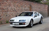
Some more information. GTA and A610 owners may switch off now. :A310 ONLY :A310

A qualification regarding front parallelism. In the ‘Service information’ at the end of the MDR is data for the Phase 2 which is probably where you found the settings shown in your first post on this thread. It does say 2 mm toe-out total for the front in static position. My understanding of static position is when the static tools are in position at the front and rear suspension. These tools are simple gauges that set the suspension in a certain position, the static position; see the attached page from the MDR.

One thing I’ve not been able to determine from the MDR is whether the car should be in the loaded condition when the gauges fit. The MDR, when referring to ride height on page J14a, states that the check is made when the vehicle is on a level surface, the fuel tank is full, tyre pressures are correct and two people are on board. Where the static tools are mentioned I can’t find any reference to the loaded condition of the car. In reality I can’t imagine static position checks being made only when two people were available and the car had a full tank of petrol.

As well as the MDR the previous owner of the car gave me a copy of a French Revue Technique for the A310 4 cylinder and V6, but only for the Phase 1. This has a drawing of the front and rear static tools, which is attached. This drawing shows some similarity to the 280 mm dimension that FAR gave you. The drawing note states that both gauges apply to the 4 cylinder and that the top gauge (AV) is also suitable for the front of the V6. It’s not too clear on the drawing but the centre distance of the two holes in the gauge is 298 mm but bear in mind that this is for the Phase 1, the 280 mm dimension you were given may be correct for the Phase 2.

Just one observation about your photo. I could be wrong but it looks as if there’s a jack under the chassis (painted grey) and something supporting the outboard end of the lower suspension arm. Even if the weight of the car is being taken by the support under the suspension arm I’d be inclined to only make the measurement when the car wheels are supporting the weight as the load point will move out and the wheel lever arm be greater. As you’ll be aware, as load is taken off the wheel the distance you’re measuring between the bolt heads reduces. I was just wondering whether the load was being taken by the wheel and not the suspension.

I’ll come back again with some dimensions I’ve taken from the top suspension arm.
You do not have the required permissions to view the files attached to this post.
1970 A110V85 and 1980 A310V6.
no avatar
User

dallarax19

Rank

Non Member

Posts

99

Joined

Tue Oct 30, 2012 1:44 am


Has thanked: 0 time
Been thanked: 1 time

Re: Need Alignment Help!

Postby dallarax19 » Wed Sep 28, 2016 8:09 pm

Hey John,

Yes! we are on the same page. The French guys provided the same tool drawing yesterday and one of my guys fabbed a pair of jigs (gauges) for me (we are a little slow in the shop at the moment). I will try them tonight. Because it is a fixed dimension I don't think it should not matter if the suspension loaded or unloaded. The easiest way to adjust everything would actually be to remove the spring. Rotate (lift) the suspension until the bolt heads meet at the 280mm mark then dial in everything. This method is a first for me but as I think through it I am finding it makes sense.

The question, is the device a "jig" or a "gauge"? I differentiate the two by saying a "jig" sets the relationship and the "gauge" checks it. So off or on wheels the "jig" will work but as a "gauge" it would need to be on the wheels. I assume it is dual purpose.


The study in the photo was to see at which point the springs start to support the car relative to the 280mm fixed dimension target. I supported the frame on jack stands and jacked up the wheel (lifted outer suspension arm) to see at which point the car would lift off of the jack stand. Low and behold it lifted way before the suspension was compressed enough to meet the fixed dimension. This is a big disappointment because it means my new Eibach springs are too tall and NG. The fuel tank has only a few gallons of fuel in it but I would be hugely surprised if fully topped off and with me in the car the front suspension would compress to spec. To your point it would require less of a force on the lower control arm if I had the jack under the tire but I was interested in the load through the upper arm so not a big deal. The load path is the same, through the steering knuckle. The main issue is I did not have enough room under the tire to place the jack.

For me to verify if this is all true I need to remove the spring, (really loving that) and use the "Jig/Guage" to rotate the suspension into place and check if I can dial in the specs. If the spring really allowed for adjusting the height I could dial in the spring load to just support the car at the 280mm fixed dimension. Because the spring is too tall it will not allow me to rotate the suspension into the service position. That is how I see it anyway, hopefully I have it right.


The Fiat is another deep dive project. I have a failed journal bearing I need to repair or replace the engine. I got a wicked rod knock at the track and it has been sitting for a couple years. I bought the Alpine to drive while I tinkered with the Fiat, it did not quite work out as planned. I don't know how you restored your car in 3 years. I am on year 5 and plan to do the Interior/Exterior trim next year to complete the project. I will keep working at it. :)
User avatar
User

johnb

Rank

Club Member

Club Member
Posts

857

Joined

Wed Sep 13, 2006 6:57 pm

Location

Cheshire


Has thanked: 13 times
Been thanked: 25 times

Re: Need Alignment Help!

Postby johnb » Thu Sep 29, 2016 12:26 pm

dallarax19 wrote:To your point it would require less of a force on the lower control arm if I had the jack under the tire but I was interested in the load through the upper arm so not a big deal. The load path is the same, through the steering knuckle. The main issue is I did not have enough room under the tire to place the jack. :)


I just lifted the front of my car with the jack under the bottom suspension arm as your photo and the checking dimension between the bolt heads decreased by 10 mm compared to when the car was just supported on its wheels. Might be worth you trying it to see if you get closer to the 280 mm dimension.

It seems that at least one other person has encountered a similar problem to yourself if you read this Retrorides story, particularly on page 2. You may have come across this site, I found it to be a good read and has some useful information. The photo Lee posted earlier in the thread is from this site.

http://retrorides.proboards.com/thread/ ... ne-a310-v6

dallarax19 wrote:For me to verify if this is all true I need to remove the spring, (really loving that) and use the "Jig/Guage" to rotate the suspension into place and check if I can dial in the specs. If the spring really allowed for adjusting the height I could dial in the spring load to just support the car at the 280mm fixed dimension. Because the spring is too tall it will not allow me to rotate the suspension into the service position. That is how I see it anyway, hopefully I have it right. :)


Another daft question but I notice that Simon Auto do the Spax/Eibach kit for Phase 1 & 2. Presumably you ordered kit 241009. How would you know whether they had actually shipped the correct kit? They don’t state any difference indicators such as spring free length. Just a thought, perhaps they could tell you the differences, diameters, wire diameter, lengths, spring rate, etc.

dallarax19 wrote:I don't know how you restored your car in 3 years. I am on year 5 and plan to do the Interior/Exterior trim next year to complete the project. I will keep working at it. :)


Perhaps I had more time and less to renovate. It was 4 years though by the time the respray was complete.

Attached are a couple of dimensions from the upper suspension arm. A little difficult to measure the 245 mm dimension on the car with the shock absorber in the way so say +/- 3mm on the dimensions.
You do not have the required permissions to view the files attached to this post.
1970 A110V85 and 1980 A310V6.
no avatar
User

dallarax19

Rank

Non Member

Posts

99

Joined

Tue Oct 30, 2012 1:44 am


Has thanked: 0 time
Been thanked: 1 time

Re: Need Alignment Help!

Postby dallarax19 » Thu Sep 29, 2016 5:26 pm

Hey John,

Thanks again. For the SPAX set Andreas (Simon) says it is correct. I asked for some key technical info like spring rates etc. Hopefully he can provide some info. I now have the gauge so I will check it with the wheels on ramps. I remembered seeing that post sometime back but did not remember the shock reference. I will check the dimensions tonight and report back to you. THX

@ Lee if you have a photo of the S2 upper control arm/radius rod attachment please post it. The FAR guys posted a triangular plate that pushes the upper control arm rearward several mm. On my car there was no plates and I don't see the same in the S1 photos..
no avatar
User

dallarax19

Rank

Non Member

Posts

99

Joined

Tue Oct 30, 2012 1:44 am


Has thanked: 0 time
Been thanked: 1 time

Re: Need Alignment Help!

Postby dallarax19 » Fri Sep 30, 2016 11:22 am

Ok just updating the post with the latest information from yesterday.

Image

Image

Image

Image

Image

It looks to me the Eibach spring is not the correct choice considering spring rate and length. I still have to verify how people actually do the suspension settings with the setting jig. I still have no confirmation how the other guys that have the SPAX Eibach set up have set their alignment nor the stock spring set up. Do people align them using the jig then just let the alignment go where ever it goes when the spring is installed? Still some open questions. I believe however the jig setting specifications are intended for the actual loaded suspension. The values are consistent , or maybe sligtly conservative, with a normal sports car setting.
User avatar
User

johnb

Rank

Club Member

Club Member
Posts

857

Joined

Wed Sep 13, 2006 6:57 pm

Location

Cheshire


Has thanked: 13 times
Been thanked: 25 times

Re: Need Alignment Help!

Postby johnb » Sun Oct 02, 2016 10:50 am

dallarax19 wrote:Ok just updating the post with the latest information from yesterday. .


Bear in mind I’m talking about my Phase 1 car but, for comparison, some more dimensions from my car relative to your photos. You could do with some dimensions from a Phase 2 car for a true comparison.

3rd photo (lhs)– With suspension unloaded spring length is 260 mm (10.23”) so similar.
3rd photo (rhs) – With wheels on the ground mine has the same 8” dimension. Note that this is with an empty fuel tank, nobody in the car and the springs are the originals.
4th photo (lhs) – From top of tyre (185/70/R13) to underside of the wheel arch outer edge is the same at 2 ½” inches. For reference, a dimension from the underside of the wheel arch edge to the top of the wheel rim is 182 mm (7 1/8”). Wheel rim is 358 mm diameter. Load condition as above.
4th photo (rhs) – I didn’t measure this as the wheel arch shapes are different.
5th photo – The 8 ¾” free length you state for the Eibach spring doesn’t seem to be in line your previous references (10” unloaded, but still with preload).

dallarax19 wrote:It looks to me the Eibach spring is not the correct choice considering spring rate and length. I still have to verify how people actually do the suspension settings with the setting jig. I still have no confirmation how the other guys that have the SPAX Eibach set up have set their alignment nor the stock spring set up. Do people align them using the jig then just let the alignment go where ever it goes when the spring is installed? Still some open questions. I believe however the jig setting specifications are intended for the actual loaded suspension. The values are consistent , or maybe sligtly conservative, with a normal sports car setting.


I think you’re right about the setting jigs. The setting of the suspension geometry needs a reference base and the jigs will provide this for uniformity. Also, it does look as if the setting jig positions are meant to replicate the normal loaded condition of the car.

In addition, in the MDR, when it makes reference to torquing the suspension fasteners; it does say that this should be done in the static position. This makes sense as the rubber part of the suspension bushes would then be in a neutral position when the fasteners are torqued. Rather than, say, torquing the fasteners with the suspension unloaded and then when the car is lowered onto the ground the flexible part of the bush is pre-torqued and continuously torqued except for when the car wheels leave the ground!

Just going back to your first post on this subject and ride heights of 135 mm front and 150 mm rear. For comparison for the Phase 1 the MDR gives values of 154 mm +/- 10 mm under the main, central chassis tube in line with the front wheels and 141 mm +/- 10 mm under the lowest point of the sump. My car measures 145 mm front and 138 mm rear.

The spring pan position on the dampers, relative to the centreline of the damper lower bolt hole, affects ride height as you know. I replaced all the dampers on the car and did record dimensional differences between the old and new rear dampers where, on the new dampers, the spring pan position was lower. I didn’t note the dimensions for the front dampers. My dampers aren’t adjustable and are Mecapart standard at the front and Record Maxigaz at the rear. All the springs are the originals.
1970 A110V85 and 1980 A310V6.
no avatar
User

dallarax19

Rank

Non Member

Posts

99

Joined

Tue Oct 30, 2012 1:44 am


Has thanked: 0 time
Been thanked: 1 time

Re: Need Alignment Help!

Postby dallarax19 » Wed Oct 05, 2016 1:51 am

Hey John,

Excellent info. I am moving on and have drawn up a new spring perch and upper spring retainer. I expect I will have parts within the next couple days. With that I can dial everything in. The Eibach spring is just too long and stiff to set the car to spec. I don't know how anyone has made it work with that combination. The photo with the 10" reference does not have any preload. The spring can be wiggled in place. What I missed verifying is that the spring did not drop down out of the rubber isolator. I will update the status in a couple days when I have it back together.

Thanks again!!
Brian
User avatar
User

johnb

Rank

Club Member

Club Member
Posts

857

Joined

Wed Sep 13, 2006 6:57 pm

Location

Cheshire


Has thanked: 13 times
Been thanked: 25 times

Re: Need Alignment Help!

Postby johnb » Wed Oct 05, 2016 10:22 am

dallarax19 wrote:I am moving on and have drawn up a new spring perch and upper spring retainer. I expect I will have parts within the next couple days. With that I can dial everything in. The Eibach spring is just too long and stiff to set the car to spec. I don't know how anyone has made it work with that combination. The photo with the 10" reference does not have any preload. The spring can be wiggled in place. What I missed verifying is that the spring did not drop down out of the rubber isolator. I will update the status in a couple days when I have it back together.


Those Eibach springs are much stiffer than the standard springs but are shorter if they were loose with the suspension hanging down. What is the actual free length out of interest?
My notes show that the free length of the front springs on my car are 330 mm (MDR states 320 mm) so they have to be compressed to fit them with the suspension unloaded. With the car on the ground they're compressed to 200 mm.
1970 A110V85 and 1980 A310V6.
no avatar
User

dallarax19

Rank

Non Member

Posts

99

Joined

Tue Oct 30, 2012 1:44 am


Has thanked: 0 time
Been thanked: 1 time

Re: Need Alignment Help!

Postby dallarax19 » Wed Oct 05, 2016 5:58 pm

Hey John,

Apologies I have not provided any real updated data. I will get all information together tonight and summarize it. My new spring parts are done too so I will give those a try to see if I can resolve the issue.

Brian
User avatar
User

johnb

Rank

Club Member

Club Member
Posts

857

Joined

Wed Sep 13, 2006 6:57 pm

Location

Cheshire


Has thanked: 13 times
Been thanked: 25 times

Re: Need Alignment Help!

Postby johnb » Wed Oct 05, 2016 7:58 pm

No apology needed. Just interested in your findings, as and when you have something of interest.
1970 A110V85 and 1980 A310V6.
no avatar
User

dallarax19

Rank

Non Member

Posts

99

Joined

Tue Oct 30, 2012 1:44 am


Has thanked: 0 time
Been thanked: 1 time

Re: Need Alignment Help!

Postby dallarax19 » Thu Oct 06, 2016 1:33 am

Hey John,

I hope this answers your questions
Image

Image

Image

Image

I need to redesign the upper spring retainer to capture the OD vs the ID and I have 7" springs on the way. The big question is what to do with the droop (unloaded suspension). I will get there with the 7" spring except for unloaded conditions like going over a sharp hill where the car could get air.
no avatar
User

MFaulks

Rank

Non Member

Posts

1552

Joined

Sun Sep 28, 2008 4:25 pm


Has thanked: 45 times
Been thanked: 26 times

Re: Need Alignment Help!

Postby MFaulks » Fri Oct 07, 2016 5:08 pm

.
Excellent thread guy's well done, I know the effort it takes to generate this kind of material, and to share, many benefit, few say thanks.... so thank you, keep it coming be good to see the results...

Cheers,
Martin
... A diamond is only a piece of coal that did well under pressure... PRV afflicted, may be I need to squeeze harder!!!!

https://www.facebook.com/maftecfaulks
no avatar
User

dallarax19

Rank

Non Member

Posts

99

Joined

Tue Oct 30, 2012 1:44 am


Has thanked: 0 time
Been thanked: 1 time

Re: Need Alignment Help!

Postby dallarax19 » Sun Oct 09, 2016 1:55 pm

Argh Amature Hour!!! I can't believe I did not check this first off but the shock travel is NG for this! The spring is sized for the available jounce. Looking at this would have save me some time.

Image

Image

Image

Image

I still need to verify it works. I also will need a helper (tender) spring to make it all work. If I can get all the dimensions accurately before the cold really settles in I will do a kinemat study like I did on my Fiat to really understand the sensitivities.
https://www.youtube.com/watch?v=K92d2j_Z-pk
https://www.youtube.com/watch?v=BvHQ-MwDgoY

If it does not work, like I blow out the shock I will engineer a proper set up.


Brian
User avatar
User

johnb

Rank

Club Member

Club Member
Posts

857

Joined

Wed Sep 13, 2006 6:57 pm

Location

Cheshire


Has thanked: 13 times
Been thanked: 25 times

Re: Need Alignment Help!

Postby johnb » Mon Oct 10, 2016 10:56 am

Thanks Martin, hopefully Brian’s thread provides interesting reading, to some at least.

Brian

I’ve been silent on this for the last few days because my knowledge of suspension design and calculations is limited, in fact, most of it learnt from Internet sources since this thread was started. However, I find the subject technically interesting enough to have an input, whether useful or not. So please forgive my continued interest and questions.

I’ve reached a point now where I’m loosing sight of what you’re trying to achieve other than make either the Eibach or Afco spring fit the space available. I’m surprised that you’re finding the spring/damper kit (presumably the Spax/Eibach combination) doesn’t appear to work straight out of the box. You’d have thought it should do if it’s supposed to be a tuning accessory for the car.

I’ve been following your dimensional checks but some of the dimensions you quote are now causing me some confusion (easily done!).

In your post of the 6th October you show dimensions and data for both the Eibach and Afco springs. In my Internet searches I also came across the Axcesspring.com calculator, which appears to be the one you used as the data table you’ve included, is exactly what you see on their calculator. Using the input data that you show in the table, I came up with the same spring rate of 60.221 N/mm (equivalent to the 343 lbf/in that you state) for the Eibach spring. I used the G value (shear modulus) of oil tempered steel to equate to your values. The other steel options they give produced slightly different spring rates. However one thing noticed is that on the photo of the spring you show a wire diameter of 13.38 mm whereas in the data table a value of 13.005 mm is used. If you input the 13.38 mm into the calculator the stiffness increases to 68.25 N/mm equivalent to 389 lbf/in.

Using the dimensions from your 6th October post for the Afco spring, rather than the dimensions from the 30th September post, gives a stiffness of 394 lbf/in. If you use your 30th September dimensions the stiffness is 355 lbf/in, similar to the 350 lbf/in that you show.

The reason I mention the stiffness is not just a check on the arithmetic but more as a comparison with the standard front springs on my car. The MDR gives Phase 1 spring data as 11 mm wire diameter, outer diameter of 109 mm, 8.1 active coils, free length of 320 mm, compressed height of 182 mm under a load of 250 daN. If you input the wire diameter, outer diameter, free length and number of coils into the Axcesspring.com calculator it gives a stiffness of 19.023 N/mm, which equates to 108.5 lbf/in. This checks out with the MDR spring compression value of 138 mm under the 250 daN load, which equates to 103 lbf/in.

Bear in mind again that this is Phase 1 data, Phase 2 suspension geometry may differ. Unfortunately the MDR doesn’t have any dimensional data for the Phase 2 springs, only a flexibility figure of 35%. This is deflection over load expressed as a % rather than expressing the spring rate as load per unit deflection. From what I know about this method of expressing spring stiffness (or flexibility) the units obviously need to be correct and they either use mm/daN or mm/kgf which is similar. For the Phase 1 springs the MDR states a flexibility of 52% which roughly equates to 138mm/250daN (0.55 or 55%) but expressed unitless as a %. So it does appear that the Phase 2 springs are stiffer, perhaps 153 lbf/in (103x52/35).

Out of interest, if you still have the original springs you could input their dimensions to the calculator to see what it gives for their stiffness.

What interests me is the large stiffness variation of the Eibach and Afco springs to the standard springs and why they are so much stiffer. I’d be interested to know the reason for this and whether it has something to do with your future use of the car such as for track use only, rather than road use. When I drive my car I don’t get the impression that the suspension is soft, it feels sufficiently firm with little roll in corners. Obviously a subjective opinion only. I can only imagine that springs of stiffness approaching 400 lbf/in would feel very firm for road use, especially when many of our suburban roads are full of pot holes. Admittedly, once you leave the towns it would be better.

A noticeable difference in the standard spring compared with the Eibach spring is its free length of 320 mm compared with 222 mm for the Eibach. This means that the standard spring has to be compressed before it can be assembled so that it is always preloaded, even when the car wheels are off the ground.

Regarding your 6th October post, this is where I’m confused about dimensions.

The second photo (lhs) states that the spring is compressed to a length of 9.125”. The photo above shows the free length as 222 mm (8 ¾”) so if it’s the same spring how can it be compressed at 9.125”?

Again about dimensions in your latest post.

Photo A – Presumably the spring is totally loose because the space available is 10” and its free length is 8 ¾” or 8.95” if the 0.197” rubber isolator is in place at the top?

Photo B – Again, how can the spring be compressed if its free length is a maximum of 8.95” as above?

I’m just trying to follow the dimensional train of thought here; maybe I’m mistaken or have misinterpreted some of the dimensions. Questions raised purely out of technical interest.

Now the Jounce block. That’s a term I hadn’t heard before. Can’t really comment here because of the questions above. Presumably the 38 – 40 mm available compression figure is measured with the damper extended to its maximum free length?

I admire your dedication and application to the task and just wonder whether there are any suspension specialists out there who might like to make some suggestions. You do seem to be having to make an extensive study and to be considering further modifications to make the combination work. This is, supposedly a standard tuning accessory. I can’t imagine anyone without your analytical approach and access to component fabrication facilities doing anything other than have the parts fitted and just accept the outcome of stiffness and ride height. As I said previously, my knowledge on the subject is limited but I’d rather throw in some observations than your thread have little feedback.
1970 A110V85 and 1980 A310V6.
no avatar
User

dallarax19

Rank

Non Member

Posts

99

Joined

Tue Oct 30, 2012 1:44 am


Has thanked: 0 time
Been thanked: 1 time

Re: Need Alignment Help!

Postby dallarax19 » Mon Oct 10, 2016 3:56 pm

Hey John,

Wow you have written quite a bit, I will respond later to address all the detail. My goal is to get the suspension geometry as close to the Alpine design position and actually lower the car a bit. Look up Roll Couple (unless you are familiar with it already) and that should give you an idea of what I am after. I apologize that I use so many terms and understand it gets confusing. I also document and post only part of the actual studies and measurements I have taken so it does look a bit random. It also gets confusing when I jump back and fourth between a loaded and unloaded condition. To make it even more challenging I am using a measurement method with significant error. I would not normally do that but I have been looking for something big that I expected to find magnitudes out of spec.

Yes my conclusion is the Spax/Eibach kit is not sized to meet the designed suspension specs. Normally an adjustable shock allows the opposite problem where the car can be lowered too much and the suspension geometry goes out of whack. This is a first for me where the shock will only raise the car.

An easy option could have been to just leave it and trim back the length of the tie rod ends and bring the toe into spec but the geometry (kinematic travel) would not be right. My end goal is to make it a touring car with occasional track use. It needs to have a performance geometry.

https://www.youtube.com/watch?v=EF1PXSGP4Vo
https://www.youtube.com/watch?v=9saUBXQOehw
https://www.youtube.com/watch?v=5b_fTOCrO-8

I will update more information later. One one final point in the spring calculations it considers the raw steel diameter so you have to subtract the coating from the calc - yes I got some odd numbers at first and after looking at it with a buddy we figured that one out. We estimated the coating to be about 0.3mm, it could be more or less. It is a guess really.
PreviousNext


  • Advertisement

Who is online

Users browsing this forum: No registered users and 19 guests

Powered by phpBB ® | Renault' and 'Alpine' are trademarks of Renault S.A.S. or its subsidiaries and are used with kind permission of Renault France