Standalone ECU Project A610

A place to showcase your pride and joy

Moderators: eastlmark, BIG_MVS, Test Moderator

User avatar
User

paulrob100

Rank

Non Member

Posts

383

Joined

Sat May 02, 2015 9:20 pm

Location

Nottingham


Has thanked: 6 times
Been thanked: 12 times

Re: Standalone ECU Project A610

Postby paulrob100 » Tue Jan 24, 2017 9:46 pm

Oops, sorry forgot its a 610.

Like Custard says, you don't know when to stop replacing things. It seems endless .
La Plastique Fantastique :GTA
User avatar
User

r5gordini

Rank

Non Member

Posts

267

Joined

Wed Nov 18, 2015 5:13 pm


Has thanked: 2 times
Been thanked: 10 times

Re: Standalone ECU Project A610

Postby r5gordini » Fri Jan 27, 2017 7:53 am

I checked the knock sensors. Both are intact so I think I will leave them alone. The knock sensor interface I bought has a LED that lights when knock is detected so I will use that when the car is running. I may even be able to use it to test them once wired in by tapping the sensors to trigger them.

Exciting stuff! Wideband O2 controller and sensors arrived. I bought the Zeitronix ZT3 from the legendary Scoff...

More wiring done. Starting to tidy up and wrap the loom then will start putting connectors on the end. I made a couple of decisions, for example will use relay(s) in the engine compartment to switch the high current feed for the coils and the injectors directly from the main power connector rather than feed high current from the fuel pump relay. Saves space in the loom!

I am also going to use a relay to switch the engine compartment fans on to avoid using a high current feed to the temperature switch.

I am sure I have forgotten a wire or two. Becomes harder to feed in once the loom is wrapped! I'm using the braided plastic sleeving stuff...

Andrew
User avatar
User

r5gordini

Rank

Non Member

Posts

267

Joined

Wed Nov 18, 2015 5:13 pm


Has thanked: 2 times
Been thanked: 10 times

Re: Standalone ECU Project A610

Postby r5gordini » Fri Jan 27, 2017 8:00 am

tmp_16579-20170125_163305~2-1682658522.jpg


I also ordered connectors for the fuel rail and supply. AN-6 to 8mm hard line (compression) and AN-6 to M14x1.5 inverted flare. The latter is important as it connects directly to the fuel pressure regulator (I'll do away with the small bit of hard line that goes from the fuel supply line to the regulator) and to the outlet from the right hand fuel rail. I will be using teflon stainless braided pipe. I worked with it before when I did my power steering conversion on my GT Turbo. It is very satisfying to work with as with little effort you can produce professional looking braided hoses.
You do not have the required permissions to view the files attached to this post.
User avatar
User

r5gordini

Rank

Non Member

Posts

267

Joined

Wed Nov 18, 2015 5:13 pm


Has thanked: 2 times
Been thanked: 10 times

Re: Standalone ECU Project A610

Postby r5gordini » Fri Jan 27, 2017 7:49 pm

And another update! Fuel injectors ordered ;-)

630cc Siemens Deka high impedance... According to the blurb:

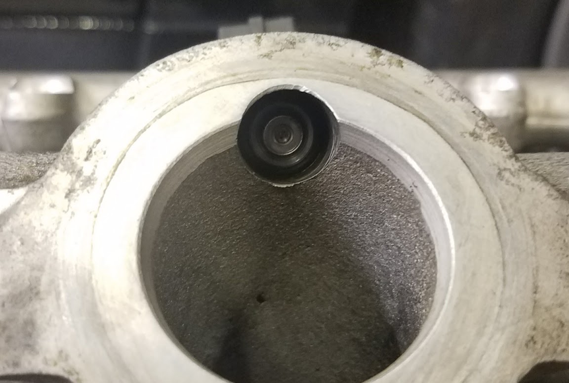
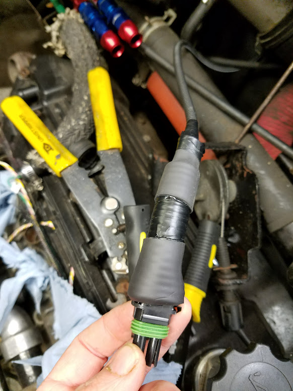
These injectors flow 60 lbs/hr at 43.5 PSI ( 3 BAR ) and up to 85 lbs/hr at 87 PSI! In addition, these units are high-impedance. Despite the high flow rate, they are linear and controllable at low pulse widths and have been used in ULEV applications! This allows you to use a larger injector than normally possible without hurting idle and low speed driveability. Adding to the flexibility of application, these units are high-impedance; making them compatible with most ECUs, while delivering the most flow available in a High-Impedance injector.

These injectors are able to function at high fuel pressures and don’t exhibit the high fuel pressure handling problems found with many other high flow high-impedance injectors. This makes these injectors very well suited to turbocharged and supercharged applications that see high fuel system pressures.

Engine performance and running quality are enhanced through the optimized spray pattern. Unlike competitors “pencil stream” high flow injectors; these High Flow injectors utilize a multi-orifice tip providing a true 30 degree spray pattern for improved mixture preparation. This results in lower BSFC and better idle quality than many injectors with less flow.


Looking forward to fitting them!

I have also decided how I am going to control the fast idle air valve... After lots of research, I will build this circuit:

http://www.glensgarage.com/3wire/

It allows direct control of the original 3-wire Bosch IAC that's fitted to the A610. Fun, fun fun! I don't have a PCB for it - I may use the prototyping area on the Megasquirt or I may just build it into a small case. I already have three other "boxes" to install!

* Megasquirt
* Zeitronix wideband O2 controller
* Knock sensor controller

... and now this.

I am also progressing with my thinking for the installation of the coils. Some may not like what I am considering, but it's only unconventional from the point of view of the materials I am thinking of using. Lightweight, strong and flexible.... (hint: not fibreglass)...

And so, back to my cold garage I go, for more wiring!

Andrew
User avatar
User

r5gordini

Rank

Non Member

Posts

267

Joined

Wed Nov 18, 2015 5:13 pm


Has thanked: 2 times
Been thanked: 10 times

Re: Standalone ECU Project A610

Postby r5gordini » Thu Feb 09, 2017 8:00 am

Sorry it's been so long since an update. I'd love to hear others' comments!

Good News! My turbo is back from the welder/fabricator - I broke a couple of studs through my own stupidity, so those have been extracted. One might need to be helicoiled in the turbine housing but I'm going to run a tap down the threads to check them - they might be ok. The stud needed to be drilled out...

I have started with the fuel hose replacement. As I measured the hard-lines, they were 8.3mm. Hard-line adapters are 8mm. I don't know whether the .3mm was due to rust, paint or whatever, but I couldn't easily get the compression fittings onto the steel pipes. By careful filing down to bare metal all round, I was eventually able to fit them:

Image

Unfortunately I slightly damaged one fitting - just due to refitting it several times - some of the anodising has come off. Doesn't affect its operation. I had to buy some spare compression olives too as my first attempts at fitting the supplied ones didn't go too well - they got stuck at the very end of the pipes and needed cutting off.

The new injectors arrived! Old:

Image

New:

Image

You can just see the multi-hole pattern in this photo:

Image

More later...
User avatar
User

r5gordini

Rank

Non Member

Posts

267

Joined

Wed Nov 18, 2015 5:13 pm


Has thanked: 2 times
Been thanked: 10 times

Re: Standalone ECU Project A610

Postby r5gordini » Thu Feb 09, 2017 8:15 am

The wiring loom around the right-hand side of the engine bay is essentially finished. TDC sensor wired up - I had to modify the plug as I couldn't buy exactly the correct one. They all had the cut-outs in the wrong places, so I cut new ones using a Dremel. It makes the plastic locating tubes more flimsy, but when it's plugged in it doesn't matter. I was very worried about the ends of the wire to the plug being vulnerable to vibration, etc., so I enclosed the end of the plug in heatshrink and a small piece of convoluted tubing so that the point of stress was transferred away from the small bit of exposed wire:

Image

Image

And my DIY cutouts (not that easy to see):

Image

Right-hand side loom before convoluted tubing:

Image

I decided to protect the left-hand side loom with fibreglass heat shielding, where it runs above the turbo. Might be overkill, but the original wires were a little bit cooked. They were surprisingly OK but I decided discretion was the better part of valour, so this is what I ended up with, which I think is quite cool:

Image

And:

Image

It's split heat trunking - has velcro to hold it together and makes a nice, neat job. Unfortunately I did get a couple of fibreglass strands caught in my fingers. Gloves next time!

I've also started connecting the new loom to the OE loom inside the car - starting with the temperature sender wires.

I'm still not sure how to mount the coils - worried about long HT leads from the left-hand rear shelf across the engine. But making up a bracket to hold them all on top of the rocker cover on the left-hand bank of the engine isn't really practical either.

Ho hum...

Oh by the way, I have decided to do without the cam sensor for now. Don't know if that's a mistake or not, but we shall see. I'm just going to batch fire the injectors. Consensus of opinion is that it makes very little difference. Maybe get slight improvements at idle and throttle transition, but Megasquirt has lots of interesting things that one can tune to enhance these bits. I'm learning lots!

One of the more interesting things is X-Tau, which is for transient enrichment. My understanding is that lots of fuel puddles on the walls of the inlet manifold and inlet into the cylinder head. You need to inject more fuel into the cylinder to compensate for that, otherwise the mixture will go lean, until the point at which all the fuel is pulled off the walls into the cylinder (eventually).

I'm sure I'm going to have fun experimenting with it!

http://www.megamanual.com/ms2/xtau.htm

Andrew
Previous


  • Advertisement

Who is online

Users browsing this forum: No registered users and 13 guests

Powered by phpBB ® | Renault' and 'Alpine' are trademarks of Renault S.A.S. or its subsidiaries and are used with kind permission of Renault France